
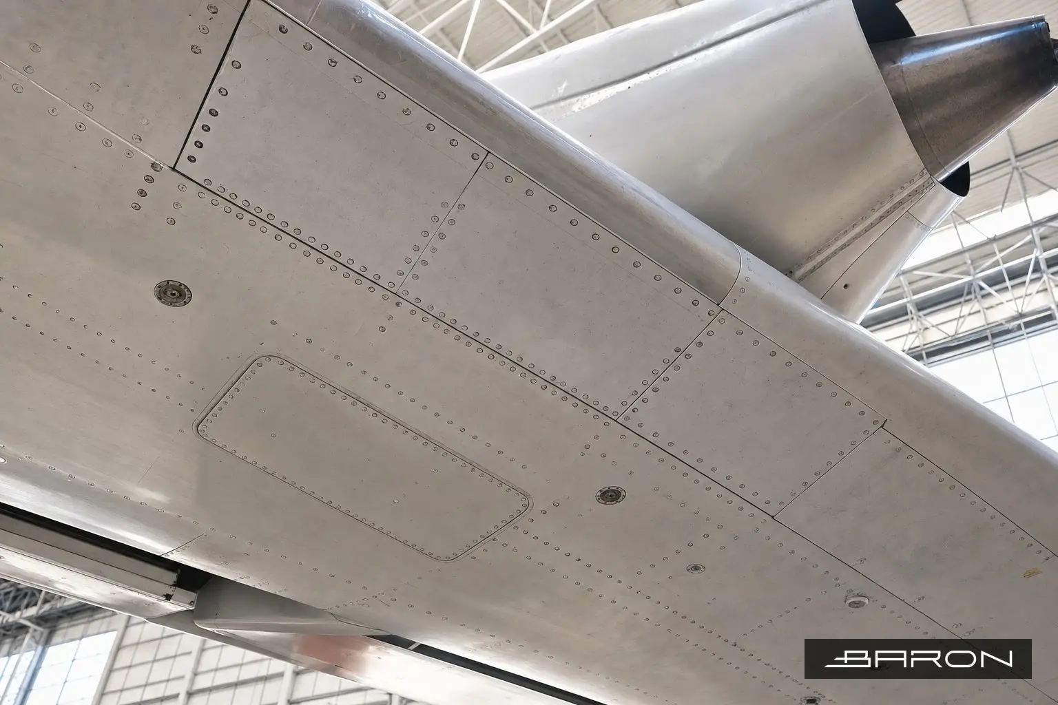
The bottom skin of the A320 outer wing, in the area directly under the pylon reinforcing plate, is one of those spots you cannot get a clean look at from the surface. The reinforcing plate, the pylon attachment hardware, and the fastener rows all sit on top of the skin you actually care about. Surface methods like eddy current and penetrant only see what is exposed. To check the skin and the fastener bores buried under the doubler, radiography is the method that earns its keep. For the X-ray side of the same family, see our radiographic inspection of outer wing buttstrap runouts.
This inspection shows up in the Airbus A320 maintenance program as a structural significant item. Load transfer from the engine pylon into the wing concentrates stress at the attachment fittings and the fastener holes that tie the reinforcing plate to the bottom skin. Fatigue cracking initiates at those bores and grows under the plate where you cannot see it. That is exactly the failure mode radiography is good at catching, because the film or the digital detector reads through the full stack of skin, doubler, and fastener.
What the task actually calls for
The A320 AMM and the relevant Airbus NDT manual define the technique: source, kilovoltage range, source-to-film distance, the IQI to use, and the acceptable density window. We set the exposure to penetrate the combined thickness of the outer wing skin plus the reinforcing plate without burning out the thinner skin at the edges of the doubler. On a stack like this the practical answer is usually a low to mid kV setting with a fine grain film or a calibrated digital detector array when access and dose limits allow it.
Image quality is not optional. We place the IQI per ASTM E1742 and ASTM E2698 for digital work and confirm the required sensitivity before any film gets read for acceptance. If the IQI wire or hole is not visible at the called level, the shot does not count, full stop. That is the difference between a record that holds up at an audit and one that does not.
Access, shot geometry, and the fastener problem
The hard part is geometry. The reinforcing plate sits on the inboard underside of the outer wing, near the pylon, and the area is crowded with structure. You rarely get a clean perpendicular shot. Cracks at fastener holes are tight and tend to run radially from the bore, so the angle of the beam relative to the crack plane decides whether you see it at all. A crack lying parallel to the beam shows as a clear indication. The same crack square to the beam can hide in the fastener shadow.
We work that with multiple exposures at different angles across the fastener rows, and we map shot locations to the fastener pattern so there is full coverage and an auditable record of what was hit. Lead markers and location stamps go on every shot. When the AMM allows it, an eddy current bolt hole or sliding probe pass complements the radiography on the accessible fasteners, but RT remains the primary method for the skin and bores under the plate. This same logic carries across the pylon-to-wing region, which is why several Airbus and Douglas structures get the same radiographic treatment.
Reading the film and dispositioning
Interpretation is where the Level II and the responsible Level III earn their certs. We are looking for crack indications at the fastener bores, corrosion thinning under the plate that reads as a density change, and any disbond or gap between the skin and the doubler. Each indication gets measured, located against the fastener map, and dispositioned against the structural repair manual. A confirmed crack drives a finding, and the operator’s engineering takes it from there to repair or a part of the SRM.
Personnel qualification follows NAS 410 and the operator’s NDT program. The radiation safety side runs to the facility’s program and the applicable regulations, and the records go into the work package so the inspection is traceable to the AMM task and the airworthiness requirement that drove it. For background on how radiography fits the broader airframe picture, our guide to radiographic testing and the ultimate guide to aircraft NDT inspection cover the method selection and zone-by-zone logic.
Why this gets done by people who do it often
This is not a generic weld shot. The exposure setup, the angle work around hidden fasteners, and the disposition against Airbus structure all take an inspector who has run the A320 pylon area before. Baron NDT runs this inspection under FAA Part 145 and NAS 410, and the same crew handles the related radiographic inspection of yoke-to-pylon attachment bolts and the eddy current work on the engine pylon front spar fittings and pylon lower link fittings at the wing. When an inspection is AD or program driven, the FAA airworthiness directive NDT compliance side matters as much as the shot itself.
If you have an A320 in for a check and need the outer wing bottom skin under the pylon plate shot and read by a team that does it routinely, call Baron NDT. We bring the technique, the qualified personnel, and the records that survive an audit. The same buried-detail challenge shows up on wing lower skin doubler and brace fitting areas, which we shoot to the same RT discipline.