The wing lower skin is a tension surface. It spends its whole life loaded in the worst direction for fatigue, and the places where a doubler or a brace fitting attaches to it are exactly the places where cracks like to start. You add fasteners, you add a step in stiffness, and you bury the critical detail under a second layer of aluminum. That stack-up is why operators call for radiography here instead of a surface method. You cannot see what is hidden under the doubler with a flashlight and a 10x loupe.
This is one of the recurring jobs that comes through our Jacksonville station, and it is worth walking through how the inspection actually runs, because the geometry is the hard part, not the physics.
Why radiography under a doubler
A doubler or a brace fitting reinforces the skin where load gets fed in or where an earlier finding was repaired. The problem is that fatigue cracks at the fastener holes can grow on the faying surface, the hidden side, long before anything shows on the outer skin. Eddy current can find a lot, and for open surface cracking it is faster, but when the suspect detail is sandwiched between the skin and the doubler, RT sees through both layers and gives you a record you can measure later. That is the trade. RT is slower and needs radiation control, but it reads the whole thickness at once.
The OEM structural repair manual and the aircraft NDT manual drive the technique. They specify source, film or detector class, the kV and exposure window, and the acceptance limits. We do not freelance the technique on a primary structure detail. We qualify it to the manual and to the governing code, generally ASME Section V Article 2 for the radiographic process and ASTM E1742 for the radiographic examination practice, then we hold to it.
The geometry problem
Shooting a doubler is not like shooting a clean butt weld. You have a variable thickness across the part: bare skin on one side, skin plus doubler in the lap, and fastener heads and tails sitting in the beam path. Pick one exposure and half the radiograph is too dark and the other half is too light. So you bracket. We set the kV and time for the thick stack-up, then verify the thin areas still read inside the acceptable density band, usually 2.0 to 4.0 on film. On a digital detector the same logic applies through the gray-level window.
Source-to-film distance matters more than people expect on these. The fastener pattern is dense, and if your geometry is sloppy the heads throw geometric unsharpness across the very crack you are trying to resolve. We push the SFD out as far as the access and the exposure budget allow, keep the source centered on the area of interest, and angle the shot when the manual calls for a specific beam direction relative to the expected crack plane. A crack that is parallel to the beam shows up. One that is square to the beam can hide. That is the whole game on fastener-hole cracking.
IQI placement and what proves the shot
Image quality indicators go on the source side, on the thickest representative section of the stack-up, so the sensitivity you demonstrate is honest for the worst case. If the penetrameter or the wire reads to the required sensitivity through the full doubler thickness, the shot is qualified. If it only reads on the bare skin, you have proven nothing about the detail that matters. We also watch for the doubler edge and fastener shadows masking a hole, and we reposition or add a second angle rather than accept a marginal frame.
Marking is its own discipline. The lower skin is large and the fastener rows look alike, so we lay out lead location markers and shoot a layout that ties every frame back to a station and stringer. When a call comes back, the repair crew has to find the exact hole. A perfect radiograph that nobody can locate on the airplane is wasted film.
Making the call
The indications we are hunting are tight fatigue cracks emanating from fastener holes, corrosion thinning on the hidden faying surface, and the occasional missing or migrated fastener. Cracks read as fine dark lines running from the hole bore, often only a few hundredths of an inch before they are reportable. Corrosion shows as a fuzzy density change rather than a sharp line. We measure, we compare against the manual limits, and we document with the IQI sensitivity and the technique on every record so the finding stands up to a quality audit and to the FAA.
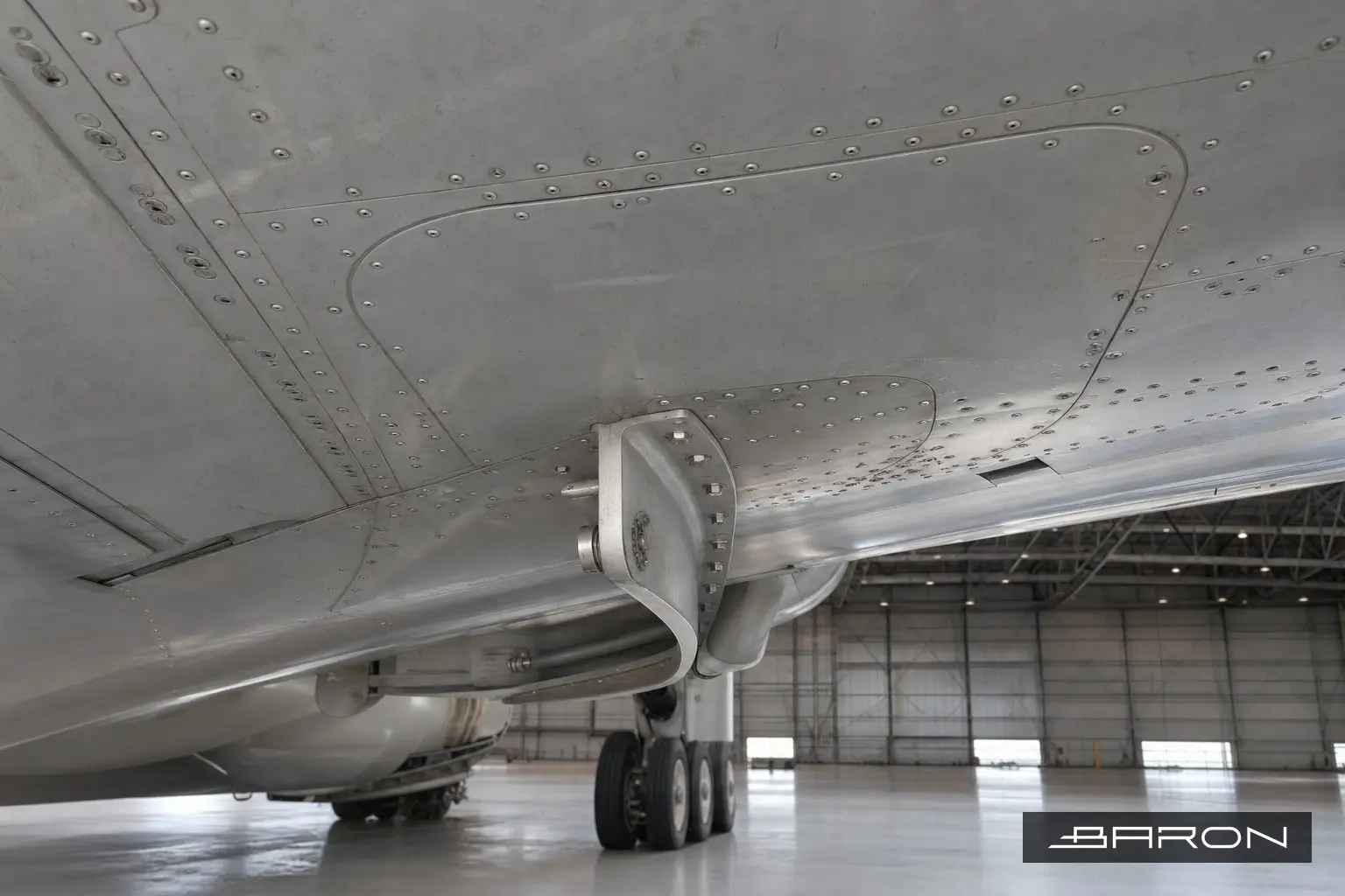
Everything here ties back to the broader discipline of aircraft NDT inspection and to the fundamentals we cover in our guide to radiographic testing. The technique is a close cousin of the work we do on the A320 outer wing bottom skin under the pylon reinforcing plate, where the buried-detail problem is the same. When a doubler also carries pylon or brace load, we often pair the RT with eddy current inspection of the surrounding fittings, and many of these shots exist to close out an airworthiness directive.
Where Baron fits
Baron NDT runs this as an FAA Part 145 repair station with personnel qualified to NAS 410. We bring radiation control, the right source and detector, and Level III oversight on the technique so the doubler shot reads true the first time. If you have wing lower skin doubler or brace fitting areas due for radiography, call us at 904-304-2907 and we will scope it to your manual and your AD status.