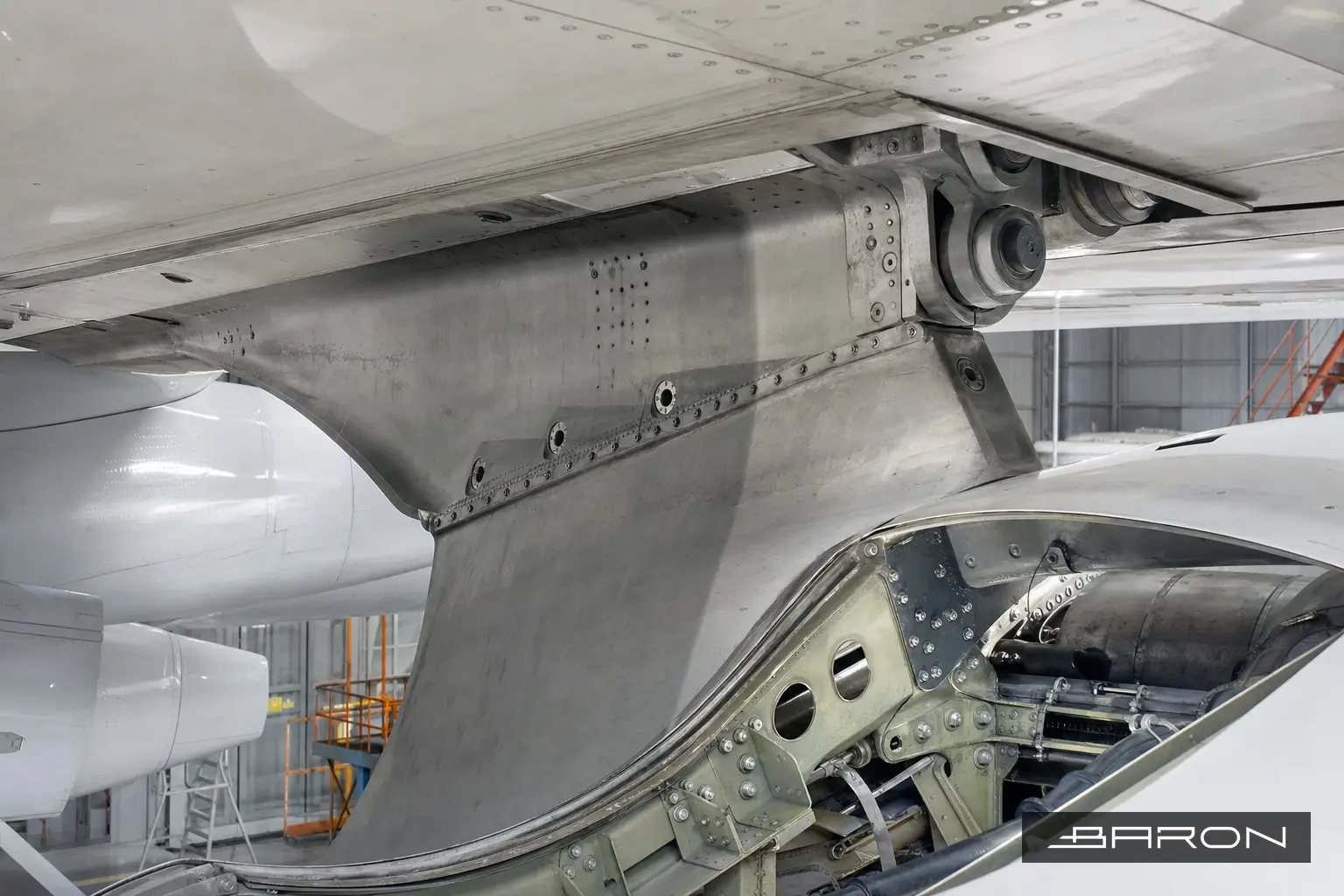
The engine pylon front spar fittings are some of the most heavily loaded structure on the airplane. They carry thrust, engine weight, and the gust and maneuver loads that get fed up through the strut into the wing. That combination of high steady load and constant cyclic input is exactly what drives fatigue cracking, which is why these fittings show up as Principal Structural Elements in the maintenance program and why the OEM NDT manuals call for recurring eddy current inspection at the front spar attach points near station FS625.3.
This is one of the recurring jobs we run at Baron NDT, and the value of the article is simple. If you operate or maintain the type, you want to know what a good eddy current crack detection job on these fittings actually looks like before the airplane goes back to service.
Why eddy current is the right method here
Pylon front spar fittings are usually high strength aluminum or, on some types, steel or titanium lugs and clevises. The cracks we are chasing start at the bore of the attach holes and at the fillet radii where the fitting transitions into the spar web. Those are buried features. You cannot see them with a flashlight and a mirror, and surface penetrant will not reach a crack that initiates at the inside diameter of a loaded hole under a pin or bushing.
Eddy current reaches them. Low frequency eddy current handles subsurface cracking through fastener heads and paint, and bolt hole eddy current with a rotating probe reads the bore of an open hole directly. The method is fast, it does not require stripping every fastener, and it gives a repeatable signal you can compare against a reference standard. For background on the physics and the probe types, our Ultimate Guide to Eddy Current Testing covers conventional ET, array, and the frequency tradeoffs in more depth.
Setting up the inspection
Every front spar fitting inspection starts with the applicable OEM NDT manual procedure, not a generic technique. The manual tells you the frequency, the probe, the scan pattern, and the reference standard for that specific fitting and station. We follow that callout, then build the setup against an EDM notch standard that matches the part geometry and the target flaw size.
Calibration is where most of the integrity of the job lives. We balance the instrument on the part, null on a flaw free area, and set the response off the reference notch so the crack signal sits where the procedure says it should on the impedance plane. Conductivity checks follow ASTM E1004 where the procedure calls for verifying the alloy and heat treat condition, because a fitting that has been reheat treated or substituted reads differently and will throw your calibration off if you ignore it.
Probe selection follows the feature. Open attach holes get a rotating bolt hole probe sized to the bore. Fillet radii and the spar web faying surfaces get a shielded surface or sliding probe. For subsurface cracking under installed fasteners we drop the frequency, accept the loss of near surface resolution, and read the deeper signal. Lift off, edge effect, and the steel of any installed bushings all have to be managed in the setup so they do not mask a real indication.
What we are actually looking for
The classic finding is a fatigue crack at the corner of a loaded attach hole, growing into the lug. We also see cracking at the fillet radius and corrosion driven pitting that becomes a crack initiation site. Any indication that meets or exceeds the reject threshold in the procedure gets marked, sized as far as the method allows, and written up. We do not clear a fitting on a borderline signal. If the response is ambiguous, we re-scan, re-null, and if needed open the area for a closer look.
Access is real work on these inspections. The front spar fittings sit behind cowling, fairings, and sometimes systems plumbing, so a clean inspection depends on getting genuine probe contact and the right scan index across the whole critical surface. A signal you could not physically reach is not a pass.
Documentation and compliance
Baron NDT runs this work as an FAA Part 145 repair station with Level II and Level III personnel qualified per NAS 410. The report records the procedure and revision, the instrument and probe, the reference standard, the calibration data, the areas inspected, and the disposition of every indication. That package is what lets the operator close the task in the maintenance program and show the inspection was done to the manual.
Pylon and strut inspections are part of a larger structural picture. If you want to see where front spar fittings fit alongside the other airframe zones, our Ultimate Guide to Aircraft NDT Inspection maps the methods by structure, and many of these fittings tie directly into airworthiness directive NDT compliance when an AD drives the repeat interval. For engine attach and shop level work, our guide to NDT in aircraft engine and MRO covers the adjacent inspections.
If you have pylon front spar fittings coming due, or an AD that calls for recurring eddy current at FS625.3, call Baron NDT. We will run it to the manual and give you a report that holds up. Related load path work is covered in our writeup on eddy current inspection of pylon track and support fittings. For the aft attachment, see our writeup on eddy current inspection of the pylon lower link fittings at the wing.