The Ultimate Guide to NDT in Aircraft Engine and MRO
Introduction
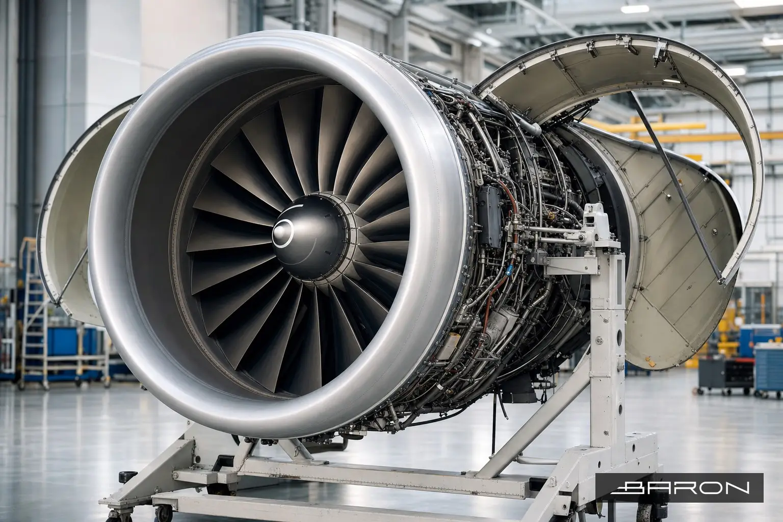
An aircraft engine is the most highly stressed assembly on the airplane. Rotating hardware spins past 10,000 rpm in a gas path that runs well above the melting point of the alloys around it, held back only by cooling air and material margins that get thinner every cycle. Nondestructive testing is how a maintenance, repair, and overhaul (MRO) shop proves that those margins are still there before the engine goes back on wing.
This guide walks through how NDT fits into the engine MRO workflow: the methods used on fan, compressor, combustor, and turbine hardware, the standards that govern the work, and the practical limits of each technique. It is written for engineers, quality managers, and MRO buyers who need to understand what a credible engine inspection program actually looks like. For the broader airframe picture, see our guide to aircraft NDT inspection, which serves as the hub for the airframe-zone methods this article connects to.
Where NDT fits in the engine shop visit
A shop visit starts with induction: the engine comes in, the records are reviewed, and the work scope is set against the operator’s needs and the OEM engine manual. The engine is then disassembled into modules, and modules into piece parts. NDT happens at the piece-part level, after cleaning and before any dimensional or repair disposition.
Cleaning matters more than people expect. Penetrant and eddy current both depend on a surface that is free of coatings, carbon, and residual fluorescent material from a prior inspection. A part that comes out of strip and clean still dirty will hide the very cracks the inspection is meant to find. Once parts are inspected and dispositioned, accepted hardware moves to assembly and rejected hardware moves to repair or scrap. Every accept, reject, and repair decision is tied back to a specific manual procedure and acceptance limit.
Methods used on engine hardware
Fluorescent penetrant inspection (FPI) on fan and compressor blades
FPI is the workhorse of the engine shop. It finds surface-breaking cracks, porosity, and laps on non-ferrous and non-magnetic parts, which covers most of the titanium and nickel hardware in a modern engine. Fan blades, compressor blades, vanes, and disks all see FPI at overhaul.
The process is the same every time: clean, apply penetrant, dwell, remove the excess, apply developer, and read the part under ultraviolet light in a darkened booth. The detail is in the discipline. Dwell times, water pressure during removal, developer thickness, and UV intensity at the part surface are all controlled and verified. Leading-edge blend repairs on fan blades are a high-volume, recurring inspection in the shop, and we cover the specifics in our article on FPI inspection of engine fan blade leading edges after blend repair. The governing process standard for aerospace penetrant is ASTM E1417, with personnel qualified to NAS 410.
Eddy current and HFEC on turbine and disk hardware
Eddy current testing is the method of choice for cracks in conductive hardware where geometry or coatings make penetrant impractical. High frequency eddy current (HFEC) concentrates the field near the surface, which makes it well suited to small features under tight tolerances: blade pin holes, dovetail and firtree slots, bolt holes, and disk rim features. A bolt-hole eddy current probe rotating inside a fastener hole will find a fatigue crack at the bore that no surface method can reach.
Eddy current also handles in-service hardware that cannot be fully stripped. The trade-off is that the inspection is local and operator-dependent, so reference standards with known EDM notches are used to set sensitivity before and during the work. The principles carry straight over from airframe work, which we cover in depth in our guide to eddy current testing.
Borescope inspection and on-wing NDT
Not every inspection requires teardown. The borescope is how a gas path gets looked at without splitting the engine, and it is the primary tool for scheduled on-wing and line checks. A video borescope feeds high-resolution images of combustor liners, nozzle guide vanes, and high-pressure turbine blades, and modern scopes can measure a defect with a stereo or shadow probe to compare against the manual limit.
Borescope findings drive the decision about whether an engine can stay on wing or needs to come off for a deeper look. It is a remote visual method, so it is governed by the same visual acuity and lighting requirements as other VT work, but the value is enormous: a five-hour borescope inspection can save a multi-week shop visit, or catch a liberated turbine blade before it becomes an in-flight shutdown.
Radiographic testing of castings and brazed assemblies
Radiography looks inside the part. In the engine world that means castings (turbine blades and vanes, structural castings), brazed assemblies, and welds. RT finds internal porosity, shrinkage, inclusions, and incomplete braze coverage that surface methods cannot reach. Investment-cast turbine airfoils with internal cooling passages are a classic RT application, where wall thickness and core position have to be verified against the drawing.
Digital radiography and computed radiography have largely replaced film in engine shops because of throughput and image handling, but the physics and the image quality requirements are unchanged. Image quality indicators (penetrameters) prove the radiograph can resolve the smallest required flaw. For the full method, see our guide to radiographic testing.
Ultrasonic testing and magnetic particle where they apply
Ultrasonic testing shows up on engine hardware for thickness measurement, bond verification, and the occasional subsurface crack inspection in thicker sections such as shafts and disks. Magnetic particle inspection covers the ferromagnetic parts that penetrant and eddy current do not serve as well, mainly steel shafts, gears, and bearing hardware. MPI is fast and sensitive to surface and near-surface cracks in steel. We cover both in our ultrasonic testing guide and our penetrant and magnetic particle guide.
Applications across the engine
Walking the gas path front to back, the inspection picture lines up roughly like this. The fan and low-pressure compressor are aluminum and titanium, so FPI and eddy current dominate, with borescope used for blade condition on wing. The high-pressure compressor adds disks and spools where bolt-hole and slot eddy current is critical. The combustor and high-pressure turbine are the hot section, where borescope, FPI on cooled airfoils, and RT of cast hardware all come into play, and where thermal fatigue cracking is the main thing being hunted. The exhaust and turbine rear frame bring structural castings and welds back to RT and FPI.
Accessory and structural hardware (gearbox parts, shafts, bearing housings) lean on MPI and UT. The point is that no single method covers an engine. A real program selects the method to the part, the material, and the expected damage mechanism.
Standards and certifications
Engine NDT lives inside a stack of requirements, and getting any one of them wrong puts the airworthiness of the inspection in question.
The controlling document for any given part is the OEM engine manual, the engine shop manual or component maintenance manual, which calls out the method, the procedure, and the acceptance limits for that specific part number. NDT does not get to choose its own acceptance criteria on a certified engine; the manual does.
Personnel are qualified and certified under NAS 410 (and the employer’s written practice), which sets the training hours, experience, vision requirements, and examinations for Level I, II, and III technicians. The process specifications behind the methods include ASTM E1417 for penetrant, ASTM E1444 for magnetic particle, the relevant ASTM eddy current and radiographic standards, and ASTM E1742 for radiographic examination practice. ASME Section V provides the general NDE methodology that underpins much of this work.
The whole operation runs under FAA 14 CFR Part 145 for the repair station and Part 43 for the maintenance itself. Baron NDT holds FAA Repair Station certificate CRS# 5NDR545D, operates an ISO 9001:2015 quality system, and carries Boeing Conformity Review approval. Those credentials are what let an operator accept an inspection result without re-doing it.
Advantages and limitations
NDT in engine MRO buys you safety and cost at the same time. It lets a shop return serviceable hardware to service instead of scrapping it, which on a set of turbine disks is a very large number. It catches fatigue and thermal damage before it liberates a part. And it produces a documented airworthiness record that survives audit.
The limits are real and worth stating plainly. Every method has a smallest detectable flaw, and a crack below that threshold will not be found, which is why inspection intervals are set with crack-growth margins rather than treated as a guarantee. Surface methods (FPI, MPI) see nothing below the surface. Eddy current is local and depends on probe access and operator skill. RT requires line-of-sight and radiation safety controls and reads volumetric flaws far better than tight planar cracks. Borescope is limited to what the gas path lets you see. Cleaning, access, and human factors drive results as much as the equipment does. A good program manages those limits with redundant methods on critical parts, not by pretending they do not exist.
Best practices
A few habits separate a credible engine NDT program from a checkbox one. Inspect to the current revision of the OEM manual, and verify the revision before the part is read, not after. Control the front end: cleaning, surface condition, and reference standards set before each run. Keep personnel current on NAS 410 vision and recertification dates, because an expired cert invalidates the work. Use reference standards with known artificial flaws to prove sensitivity at the start and during long runs. Document the technique, the equipment, and the result against the part and the work order so the record stands on its own. And when a part is critical and a single method has a known blind spot, layer a second method rather than accepting on one.
Operators who outsource this work get the same benefit without carrying the equipment and personnel overhead. We cover the economics in our article on outsourcing NDT in aviation MRO.
Frequently asked questions
What NDT methods are used on aircraft engines?
The core methods are fluorescent penetrant (FPI) for surface cracks on titanium and nickel parts, eddy current and HFEC for cracks in conductive hardware and around holes and slots, borescope for gas-path visual inspection, radiography for internal flaws in castings and welds, and ultrasonic and magnetic particle for steel shafts, gears, and thicker sections. The method is chosen to the part, the material, and the damage mechanism.
Why is FPI so common in engine overhaul?
Most engine hardware is non-magnetic titanium or nickel alloy, where magnetic particle does not apply. FPI is sensitive to surface-breaking cracks, fast, and able to inspect complex geometry all at once, which makes it the default for fan and compressor blades, vanes, and disks. It is governed by ASTM E1417 with personnel certified to NAS 410.
Can engine inspections be done without disassembly?
Yes, up to a point. Borescope inspection lets a technician look at combustor liners, nozzle guide vanes, and turbine blades through existing ports while the engine stays on wing. It is the primary on-wing method and often decides whether a deeper teardown is needed. It cannot reach disk bores, slots, or internal cast features, so those still require piece-part inspection at overhaul.
What standards govern engine NDT?
The OEM engine or component manual sets the method and acceptance limits for each part. Personnel are certified to NAS 410, processes follow ASTM E1417 (PT), E1444 (MT), E1742 (RT) and the relevant eddy current standards, and ASME Section V provides general NDE methodology. The repair station operates under FAA Part 145 and Part 43.
How does NDT save money in MRO?
NDT lets a shop confidently return expensive serviceable hardware to service instead of scrapping it, and it catches damage early when a repair is still possible. On rotating hardware like disks and shafts, the value of a correct accept decision is substantial, and the documented record protects the operator at audit.
Conclusion
Engine MRO is where NDT earns its keep. Every accept, reject, and repair decision on a piece of rotating hardware traces back to an inspection, a procedure, and an acceptance limit, and the airworthiness of the engine rests on getting those right. The methods are mature, but the results still depend on clean parts, current procedures, certified people, and the discipline to layer methods where one has a blind spot.
Baron NDT is an FAA Part 145 repair station (CRS# 5NDR545D) and a service-disabled veteran-owned small business performing engine and airframe NDT for MRO operators across aviation. If you need FPI, eddy current, borescope, or radiographic inspection on engine hardware, or a partner to handle overflow during a heavy shop-visit season, reach out at 904-304-2907 or through baronndt.com to talk through your work scope.