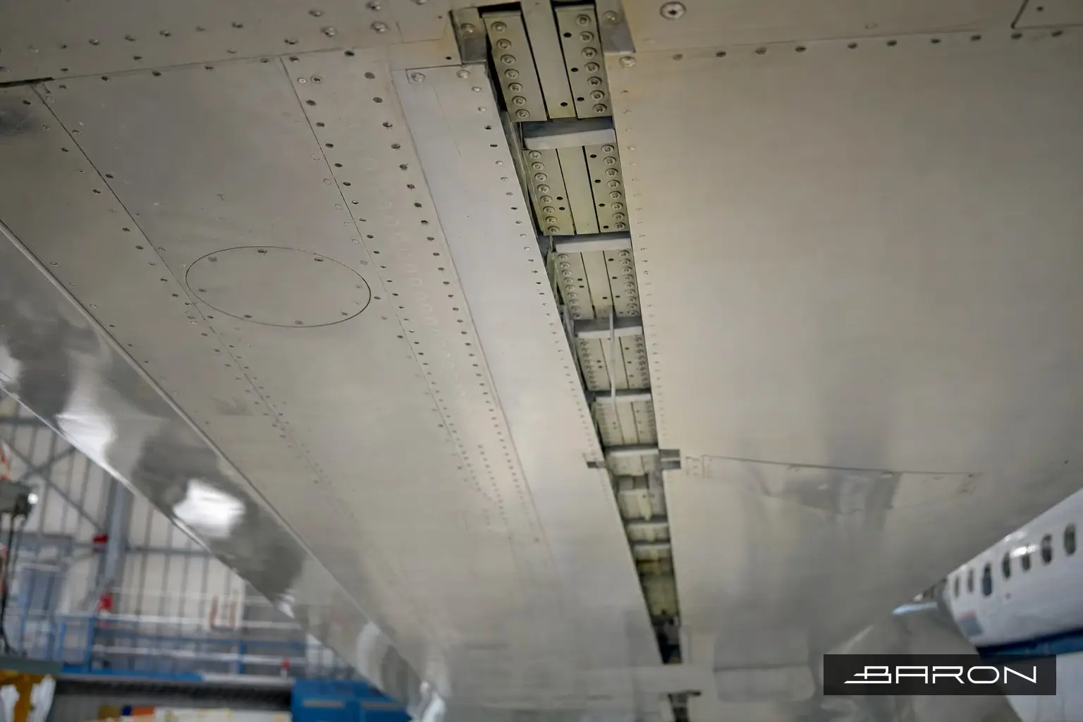
The buttstrap is the part nobody sees and everybody worries about. On the A320 family outer wing, the lower skin panels are joined by an internal splice strap, and the ends of that strap taper down to a runout where the load transfers back into the skin. That runout is a fatigue site. The fastener rows there carry high bearing loads, the strap steps down in thickness, and the whole joint sits buried under the skin where you cannot get a probe on the layer that matters. That is why the inspection comes to radiographic testing instead of a surface method.
People ask why we do not just run eddy current here. Eddy current is excellent on the outer surface and around open fastener holes you can reach. The problem at the buttstrap runout is the part of the joint you care about is the second and third layer down, the strap itself and its fastener holes, not the skin you can touch. Surface and near-surface methods lose sensitivity fast through that stack. X-ray sees through the whole joint and puts the strap, the fastener shanks, and any cracking emanating from the holes onto one image. For a hidden multi-layer splice, that is the method that actually answers the question.
What the runout is actually doing
A buttstrap is a doubler that bridges two skin panels so load passes across the joint through the fasteners rather than across a gap. At the runout, the strap thins out over a few fastener pitches so the stiffness change is gradual. Gradual is the goal, but the last few fasteners before the strap ends still see a stress concentration. Cracks that start there grow along the fastener row, hole to hole, hidden under the skin the entire time. By the time anything would show on the outer surface the crack is already long. RT catches it while it is still at the hole, which is the whole point of inspecting on a schedule instead of waiting for a finding.
How we shoot it
The geometry drives everything. You want the X-ray beam lined up with the fastener row so cracks growing in that plane open up on the film or the detector instead of hiding behind a fastener head. We work the source-to-film distance and the angle off the Airbus NDT manual technique for the specific zone, and we place image quality indicators per ASTM E1742 so the shot proves its own sensitivity. If the IQI hole or wire you need to resolve is not there, the radiograph is not acceptable, full stop. We shoot a penetrameter that matches the total thickness through the joint, skin plus strap, not just the skin.
Access on the outer wing is tight and the part is curved, so a single flat shot rarely covers a long runout cleanly. We index along the row and overlap the frames so no fastener falls in a gap between exposures. Digital detectors help here because we can check each frame for coverage and density before we move, instead of finding a hole in the coverage back at the darkroom. Where the manual still calls for film, we shoot film and process to the density and IQI the technique sheet specifies.
Reading the radiograph
A fatigue crack at a fastener hole shows as a fine line running off the bore, usually toward the next hole or toward the strap edge. The trick is separating a real indication from the normal hardware in the shot: fastener shanks, the strap edge, sealant, and the skin lap all throw lines and density changes that an untrained eye can call a crack. This is where a Level II or III who has read this joint before earns the job. We compare row to row, check whether a line tracks across multiple exposures the way a real crack would, and we use the IQI to confirm we had the sensitivity to find what the spec requires. Corrosion shows up too, as thinning or a mottled density change across the strap, and the same shot that finds cracking will flag material loss before it gets structural.
Why it lands with Baron
This is an FAA Part 145 inspection with NAS 410 certified personnel, written technique sheets, and records that hold up. The same buttstrap family shows up in our phased array work on A220 bottom cover runouts (57-21-57), and the radiographic approach is the same thinking we bring to wing lower skin under doubler and brace fittings and to the A320 outer wing bottom skin under the pylon reinforcing plate: get the beam on the plane that matters, prove sensitivity with the IQI, and read the joint with someone who knows what the hardware looks like. For the bigger picture on where RT fits across the airframe, see our guide to aircraft NDT inspection.
If you have outer wing buttstrap inspections coming up on an A320 family aircraft, or any hidden splice that needs X-ray, call Baron NDT. We will work the technique to your NDT manual and turn around records you can put in the logbook.