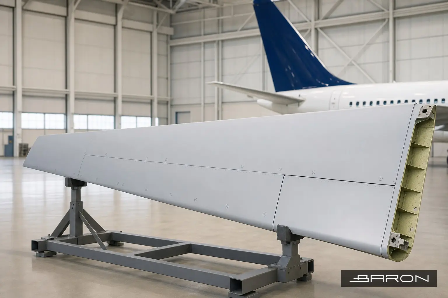
Flight control surfaces are where honeycomb sandwich construction earns its keep. Rudders, elevators, ailerons, spoilers, and flaps are built light and stiff by bonding thin composite or aluminum face sheets to a thin-wall honeycomb core. That same construction is also where damage hides. A crushed cell, a disbond between the skin and the core, or water sitting in the cells will not always show on the surface, and a tap test only tells you so much across a large panel. Infrared thermography is the method we reach for when we need to map the whole surface and see what is happening underneath it.
This is a core specialty at Baron NDT, and most of the honeycomb work we do lives on Airbus and Boeing control surfaces. It is one part of a broader composite and honeycomb inspection program, and it fits inside the wider aircraft NDT inspection picture across the airframe. Here is how the inspection actually runs and what we are looking for.
Why honeycomb fails the way it does
The failure modes on a bonded sandwich panel are pretty consistent. Skin-to-core disbond is the big one, usually from impact, fatigue, or a bondline that was marginal to begin with. Crushed or buckled core shows up after a tool drop or ground handling contact. And water ingress is the slow killer. Once moisture gets past a damaged edge seal or a fastener hole, it pools in the cells, adds weight, freezes at altitude, and drives further disbonding every cycle. The OEM nondestructive test manuals call these out by zone, and Airbus structural repair documentation such as the rudder and elevator chapters under the 55 ATA series gives the inspection thresholds and allowable limits.
None of those defects need to break the surface to matter. That is the whole reason a full-field method beats spot checking.
How thermography sees a disbond
Active thermography works on a simple idea. You put a small, controlled pulse of heat into the surface and watch how it flows away with an infrared camera. In a sound area, heat conducts smoothly into the structure behind the skin. Over a disbond or an air gap, the heat has nowhere to go, so that spot stays warmer for a fraction of a second longer and lights up in the thermal sequence. Water does the opposite. It has high thermal mass, so a wet cell pulls heat out of the skin and reads cooler than the dry area around it.
Most of our flight control work uses flash thermography, where a pair of xenon flash heads deliver the heat pulse and the camera captures the cooldown at high frame rate. The raw frames are useful, but the real information comes out of post-processing. Thermographic signal reconstruction and first-derivative analysis pull faint disbonds out of the noise that you would never catch watching the live image. For thicker or deeper structure, lock-in thermography trades speed for depth by modulating the heat input.
If you want the full method background, our complete guide to infrared thermography for composite inspection covers the flash versus lock-in tradeoffs in more depth.
Running the inspection
The surface prep is light, which is one of the reasons thermography is attractive on a busy hangar floor. No couplant, no penetrant, no consumables soaking into the part. We clean the area, mask off reference points, and shoot in overlapping frames so the whole control surface gets covered with consistent heat input. A matte panel reads cleanly. High-gloss paint can throw reflections, so we manage the angle and sometimes apply a removable thermal coating on problem areas.
Calibration matters as much as the hardware. We set up on a reference standard with known disbond sizes so the flash energy, camera distance, and frame timing are dialed to the panel thickness we are actually inspecting. A thin aileron skin and a thick rudder section do not get the same setup. We document the parameters per panel so the inspection is repeatable on the next visit and the records stand up under a Part 145 audit.
For honeycomb specifically, the read is direct. Disbonds and crushed core show as warm anomalies that hold heat. Trapped water shows as cool, often cell-shaped pockets following the core pattern. Edge seals and close-out areas get extra attention because that is where moisture gets in first.
Where thermography fits next to other methods
Thermography is fast and full-field, but it is not the only tool. A tap test is still a quick confirmation on a small suspect area, and an inspector with a good ear catches obvious disbonds, but it does not scale across a six-foot rudder and it tells you nothing about water. We compare approaches in thermography for disbond detection in Airbus rudder bonded skins and walk through a full surface map in our elevator composite panel inspection writeup. When thermography flags something marginal, we will back it up with ultrasonic bond testing or, for water confirmation, X-ray, which images the dense moisture directly.
The point is to use thermography for what it does best, which is screening a large surface fast and pointing the more localized methods at the spots that need a closer look. On the engine side, the same logic applies to nacelle and cowl composite, which we cover in engine fan cowl thermography.
Personnel and records
Thermographic interpretation is judgment work, so personnel qualification per NAS 410 is not optional. Reading a derivative thermogram and separating a real disbond from a paint thickness change or a stiffener shadow takes a qualified thermographer. Every inspection leaves a documented report with the thermal images, the defect map referenced to the part, the calibration parameters, and the disposition against the OEM limits. That record is what the operator and the OEM stand behind, and at a Part 145 shop it is part of the package.
Bottom line
If you are dealing with a bonded honeycomb control surface and you suspect disbond, crushed core, or water in the cells, thermography gives you a full-surface picture without tearing into the part. Baron NDT runs this work on Airbus and Boeing flight control surfaces day in and day out. If you have a rudder, elevator, or aileron you need looked at, we can take the inspection and get you a report you can act on. These techniques are accepted methods when qualified, as covered in our look at thermographic inspection per AC 43.13-1B.