Turbine engine fan blades live in one of the most punishing fatigue environments on any airframe. The dovetail root that anchors each blade into the fan disc, along with the pin holes and bolt holes that locate retention hardware, sees a relentless combination of centrifugal load, vibratory stress, and fretting at the contact faces. As a Level III reviewing these inspections, I treat the dovetail and its associated holes as priority crack-initiation sites every time a blade comes through the shop. High-frequency eddy current (HFEC) inspection is the method we lean on to find tight surface and subsurface fatigue cracking in these features before they propagate to failure.
Why Dovetail Roots and Pin Holes Crack
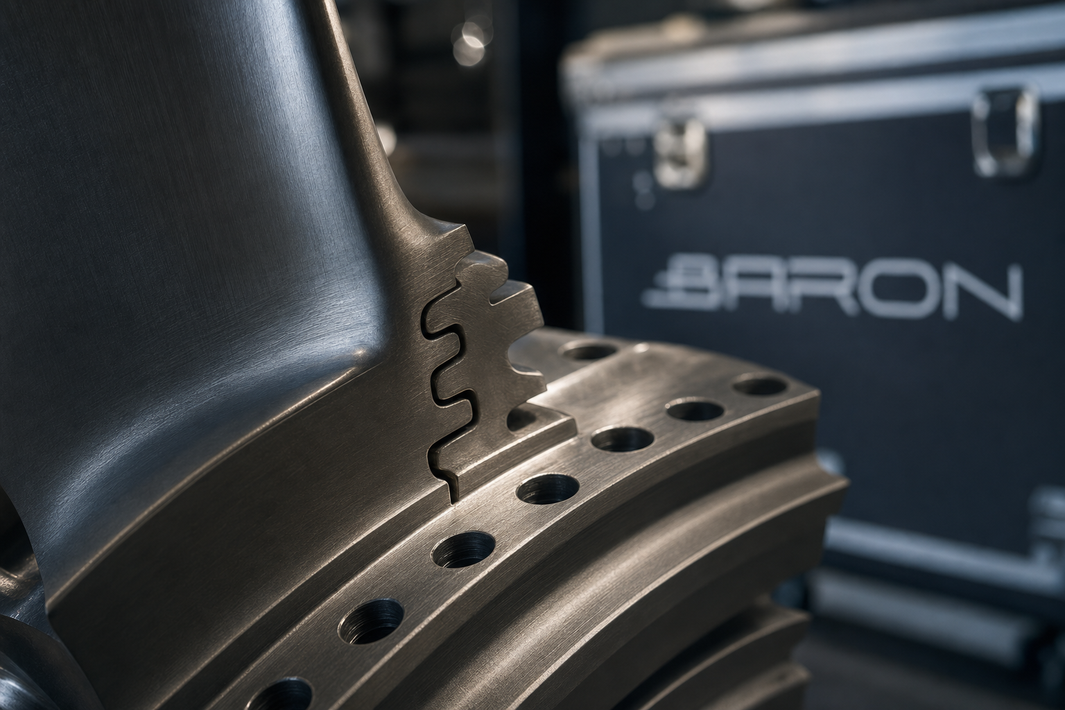
The fir-tree or dovetail geometry that retains a fan blade concentrates stress by design. Each lobe of the root carries a share of the centrifugal pull, and the radii between lobes act as classic stress raisers. Add the alternating bending from aerodynamic excitation and you have a textbook high-cycle fatigue scenario. The contact faces between the blade root and the disc slot also experience micro-motion under load, which produces fretting. Fretting damage roughens the surface, removes protective coatings, and seeds micro-cracks that high cyclic stress then drives deeper.
Pin holes and bolt holes carry their own risk. Bore surfaces are loaded in bearing, the hole edges concentrate stress, and any tooling marks or corrosion pits left from manufacture or prior service become crack nuclei. Cold-worked holes resist this better, but they are not immune, which is exactly why operators run repetitive HFEC checks on fastener and pin holes across the fleet. Our team has documented similar bore-cracking behavior in the Airbus A320 cold-worked fastener hole HFEC inspection, and the physics on a fan blade pin hole is no different.
How HFEC Finds the Cracking
Eddy current testing induces circulating currents in a conductive part using an alternating-current coil. A surface-breaking crack interrupts those currents, and the resulting change in coil impedance shows up on the instrument as a deflection on the impedance plane. Running at high frequency, typically in the hundreds of kilohertz up into the low megahertz range, concentrates the eddy currents near the surface where fatigue cracks initiate. That shallow penetration is a feature, not a limitation, because it sharpens sensitivity to the tight, surface-breaking indications we are hunting on titanium and nickel-alloy blade roots. For a fuller treatment of the underlying physics, see our complete guide to eddy current testing.
Geometry drives probe selection. Dovetail radii and lobe flanks call for shaped surface and contour probes that follow the profile and hold a consistent liftoff. Pin and bolt holes are inspected with bolt-hole probes, often spun in a rotating scanner so the coil sweeps the full bore at a controlled rate. The rotating approach gives a repeatable, high-resolution scan of the bore wall and the critical edge radii where cracks like to start. Calibration is performed on a reference standard carrying EDM notches of known depth that represent the rejectable flaw size for that feature, and the technician sets phase and gain so the notch responses are unambiguous against the background.
Surface Preparation and Reference Standards
HFEC is sensitive, and that sensitivity cuts both ways. Loose scale, heavy soils, or thick coatings produce liftoff noise that masks real indications, so blade roots are cleaned and, where required, stripped before inspection. We document the surface condition and any coating left in place because coating thickness affects effective liftoff and must be matched on the reference standard. Our procedures are written to the eddy current consensus standards, principally ASTM E309 for eddy current examination using the impedance plane method and ASTM E1004 for electromagnetic conductivity measurement, alongside the engine manufacturer non-destructive test manual that governs the specific part. The notched reference standard, the frequency, the probe, and the scan plan are all locked to that manual so results are traceable and repeatable.
What the Indications Look Like
A genuine fatigue crack produces a sharp, repeatable impedance deflection that holds its phase angle as the probe passes over it and reproduces on a second pass. We separate that from liftoff variation, which trends along the liftoff direction on the impedance plane, and from benign features such as edge effect at a radius or a conductivity change from a coating step. On a rotating bore scan, a crack shows as a localized signal that recurs at the same angular position every revolution. Sizing against the calibrated notch lets us call the indication relative to the rejectable threshold rather than guessing from amplitude alone. Every reportable indication is mapped, photographed where access allows, and dispositioned against the manual.
Why HFEC Beats Penetrant in Tight Bores
Fluorescent penetrant inspection remains a workhorse for open blade surfaces, and we use it heavily, including the FPI of fan blade leading edges after blend repair. But penetrant struggles inside a tight-radius pin hole or a deep dovetail slot. You cannot reliably see fluorescence at the bottom of a small bore, developer can bridge tight cracks, and the process needs line-of-sight under UV. HFEC, by contrast, reaches into the bore on a rotating probe, reads the full circumference without optical access, and does not depend on a crack being open enough to bleed dye. For bore and tight-radius scanning, eddy current simply detects what penetrant cannot see. The trade-offs between the surface methods are laid out in our guide to penetrant and magnetic particle testing.
Qualified People, Qualified Facility
Method capability means nothing without qualified people behind the probe. Baron NDT technicians are certified to NAS-410 in eddy current, with Level III oversight of procedures, calibration, and final disposition. The work is performed within an FAA Part 145 repair station framework, so the inspection records, calibration traceability, and reporting meet the documentation rigor that operators and primes expect on engine hardware. This fan blade dovetail and pin-hole work runs at our Jacksonville, Florida aviation facility, which is built around engine and component NDT. If you are scoping a broader engine workscope, our guide to NDT in aircraft engine and MRO and the broader aircraft NDT inspection hub show how HFEC fits alongside the other methods we run.
Fan blade dovetails and pin holes do not announce their cracks. They fail quietly, at the radius or the bore edge, after thousands of cycles of load and fretting. High-frequency eddy current gives us a sensitive, repeatable, and traceable way to find that damage early, and pairing it with qualified technicians and a Part 145 framework keeps the engine flying safely.