The fuselage lap seams above the aft cargo door take a beating that the rest of the skin does not. Pressurization cycles load the longitudinal splices, the cargo door cutout concentrates stress around the corners, and the upper rivet row is the first place fatigue shows up. That combination is why these joints sit on so many NDT work cards, and why phased array ultrasonic testing has become the method of choice for getting under the skin without pulling fasteners.
When we set up a 737 lap seam phased array inspection, the goal is specific: find cracks growing from the upper fastener row of the lap splice, plus any edge fraying or corrosion thinning, while the skin stays on the airplane. The 737 NDT Manual chapter that governs lap joint inspection lays out the scan zones, the reference standard, and the accept/reject criteria. We work to that document and to the operator’s approved program, not to a generic procedure.
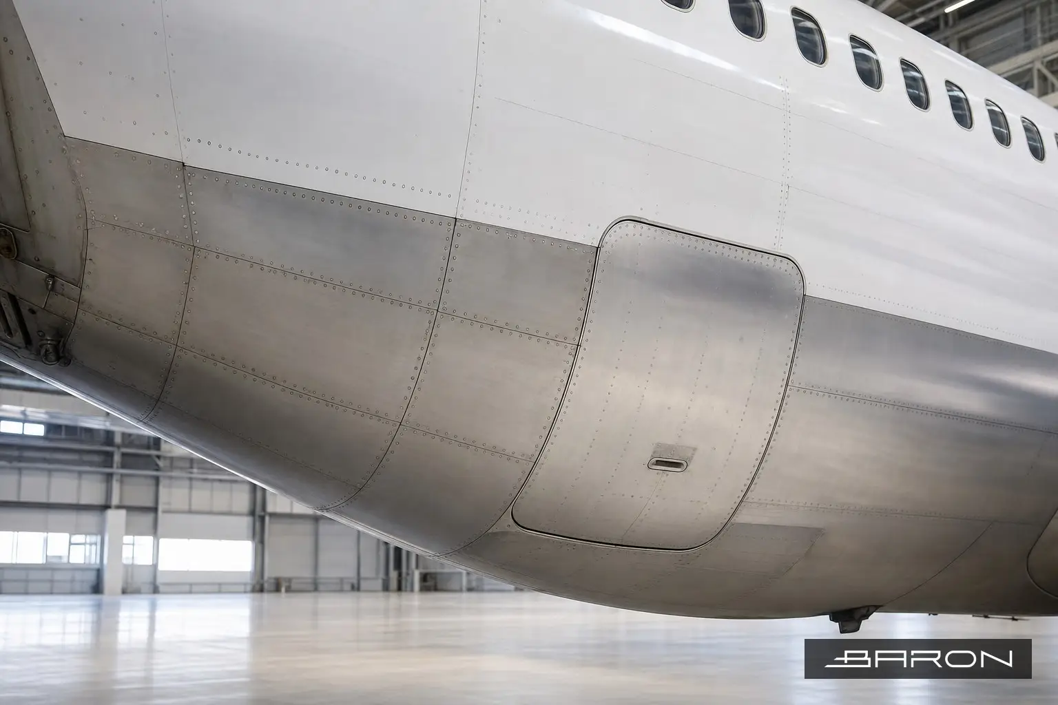
Why the aft cargo door area cracks first
Lap splices carry hoop stress across two skins joined by rivets. The inner skin sees the higher load at the upper rivet row because that is where the faying surfaces transfer the most shear. Add the geometric jump of the cargo door cutout and you get a local stress riser. Over thousands of flight cycles, small cracks initiate at the fastener holes and run along the rivet line. Left alone they link up into multi-site damage, which is the failure mode that drove the industry-wide lap splice focus after the early fuselage events and later AD activity such as AD 2023-13-05 and SB 737-53-1399. Our deeper look at that compliance work is covered in our writeup on 737NG lap splice NDT for AD 2023-13-05.
Why phased array over a single-element probe
Conventional ultrasonic and high frequency eddy current both have a place on lap joints. Phased array earns its spot when you need to image the crack, size it, and document where it sits relative to the fastener. A linear array with an electronic sweep covers the full fastener row in one pass instead of indexing a single crystal hole by hole. The sectorial and linear scans give you a cross-section of the joint, so a crack running from the upper rivet hole shows up as a tip diffraction signal you can measure against the calibration reflector. That repeatability matters when the airplane comes back for the next interval and an inspector has to compare growth.
We calibrate on a representative reference standard that matches the skin thickness and fastener pattern, set the gain to the response from the reference notch or side-drilled hole, and verify the wedge delay before the first production scan. Encoder-driven scanning ties each indication to a position, so the report shows exactly which fastener bay holds the call. The same discipline carries over from our other Boeing work, including phased array crack detection per 737 NDT Manual 53-30-06.
The scan, step by step
Surface prep comes first. The skin gets cleaned so the wedge couples cleanly, and any sealant or paint buildup that would lift the probe gets noted. We confirm the fastener layout against the work card so the scan plan covers the upper row, the lower row, and the skin between them where corrosion can sit. The array sweeps along the splice with couplant and an encoder, and the operator watches the live S-scan and C-scan for crack tip signals and for loss of back wall that flags thinning.
Indications get sized, marked, and photographed. Anything at or over the manual’s rejectable limit goes into the report with its position, length, and depth. We do not guess on borderline calls. If a signal is ambiguous, we rescan from the opposite direction or back it up with HFEC around the fastener head, which is the same complementary approach used in eddy current array work on 737 crown skin.
Documentation that holds up
A lap seam call is only useful if the maintenance team can act on it and the records survive an audit. Our reports tie each indication to the fastener bay, list the equipment and calibration block, and reference the manual revision used. Personnel are qualified to NAS 410 and work under Baron’s written practice, and the whole job runs inside our FAA Part 145 repair station system. For the wider picture of where this fits in an airframe inspection program, see our guide to aircraft NDT inspection, the ultrasonic testing pillar, and the guide to FAA AD NDT compliance.
If you have 737s coming due for lap joint or cargo door surround inspections, Baron NDT can run the phased array scans on-wing or in the hangar and turn around documentation your DER and your records team can use. Call 904-304-2907 to schedule.